Making a track timer
I learned a lot during this project.
First Steps
I did well in my electrical and computer engineering class, and I have soldered before, but there were a lot of steps to go from the idea to a finished project. The first step was simply knowing what parts to buy. I outlined these parts in the project post, which is linked above or in the project tab. After getting a shopping list, the total price for this project was roughly $90, well within my budget.
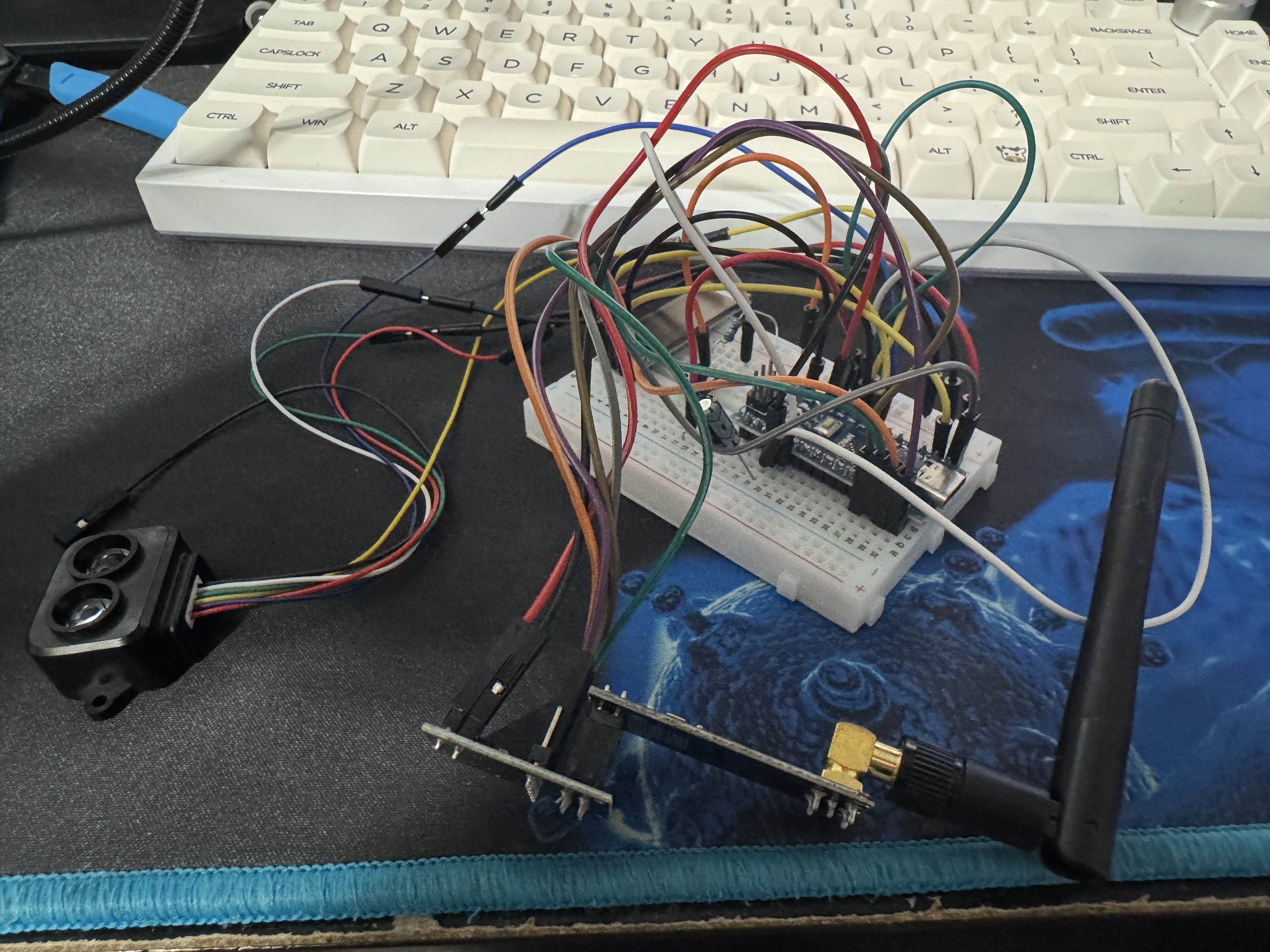
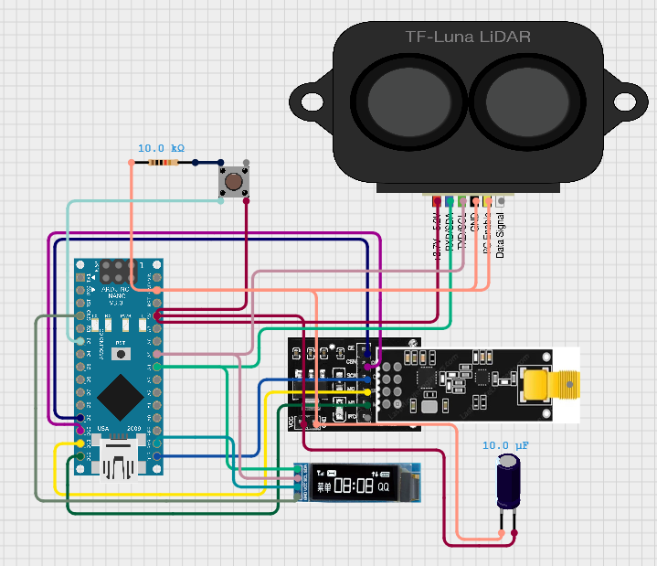
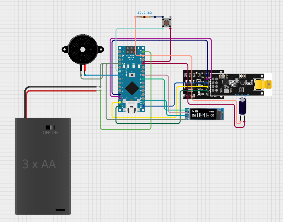
I love Arduinos, they make this sort of project much more affordable. I found out they made Arduino Nanos with USB Type-C, so I bought 2 of them. Connecting everything to the breadboard was mostly accomplished by watching videos of people using similar hardware, and using wiring diagrams I could find.
While researching the nRF24L01 wireless module, I heard many people having reliability issues, mostly due to power problems. I used a breakout adapter with an onboard 3.3V regulator, as well as a 10μF capacitor soldered between the power and ground. I had no issues with reliability, and thankfully getting the modules to communicate was pretty painless.
Three libraries need to be included:
#include <SPI.h>
#include <nRF24L01.h>
#include <RF24.h>
The pins need to be defined, as well as the address, which can be anything as long as its the same on both:
RF24 radio(9, 10);
const byte address[6] = "TIMER"
The setup block needs a few things to get the radio started:
void setup(){
    Serial.begin(152000);
    radio.begin();
    radio.openWritingPipe(address);
    radio.startListening();
}
Once the radio is setup and listening, sending a message is fairly straightforward. Within the loop block, we need to check if there is a radio signal available. If there is, you can read the message with radio.read(). This could be anything, but in the end I went with a long as my data type. I first assembled and tested this, sending the message “GO”, and sometimes the receiver would not get the message. I figured a fix for this would be to repeatedly send the current time for a brief moment, so if any message is lost, the receiver can simply start at whatever time was received. Receiving the message looks like the following:
if (radio.available()){
    unsigned long receivedTime = 0;
    radio.read(&receivedTime, sizeof(receivedTime));
    timer = millis();
}
And sending the repeated messages looks like this within the loop block:
if (raceStarted && !raceStopped) {
    unsigned long raceTime = millis() - startTime;
    radio.write(&raceTime, sizeof(raceTime));
    delay(1);
  }
Now, the program starts when a button is pressed, repeatedly sends the current time to ensure they properly sync, and starts timing once it receives the current time. All that is left is to set up the LiDAR sensor properly.
Reading the LiDAR sensor is pretty simple after reading some documentation and viewing some example code, I came up with this block of code for reading the sensor data, and triggering the end of the race:
if (tflI2C.getData(tfDist, tfAddr)) {
      if (tfDist > 0 && tfDist < triggerDistance) {
        raceStopped = true;
        showMessage("FINISHED", buf);
      }
    }
After writing some more code to make the program more usable by implementing the buzzer and adding a countdown sequence, I had a working program on some breadboards.
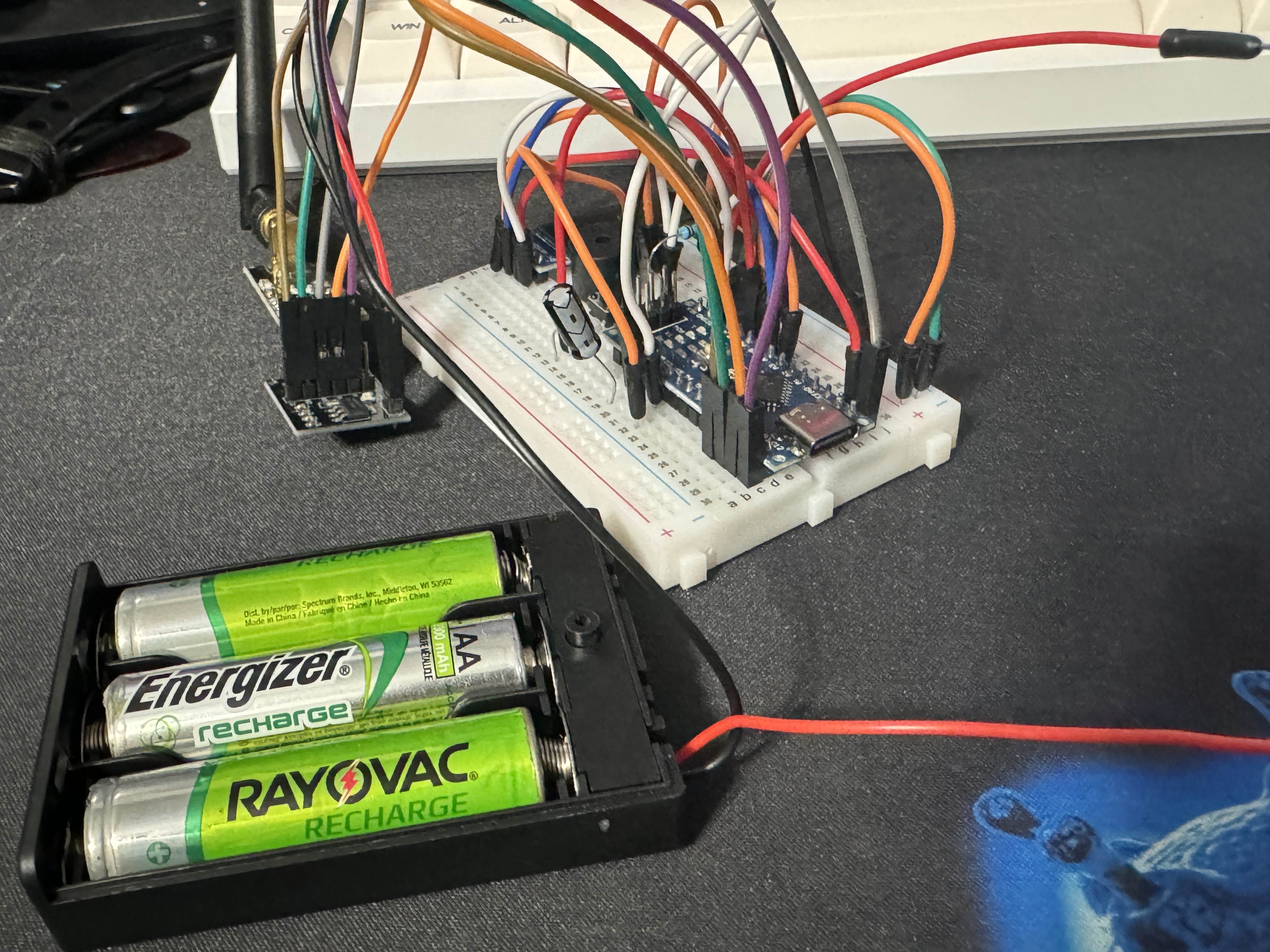
Once I had those breadboard prototypes created, I took them in a shoebox to the track to test and make sure that they work. They worked in close range, so the only limit left to test was the radio modules’ capabilities of range. They worked well, so the next step was to solder them to a board and design a case for them.
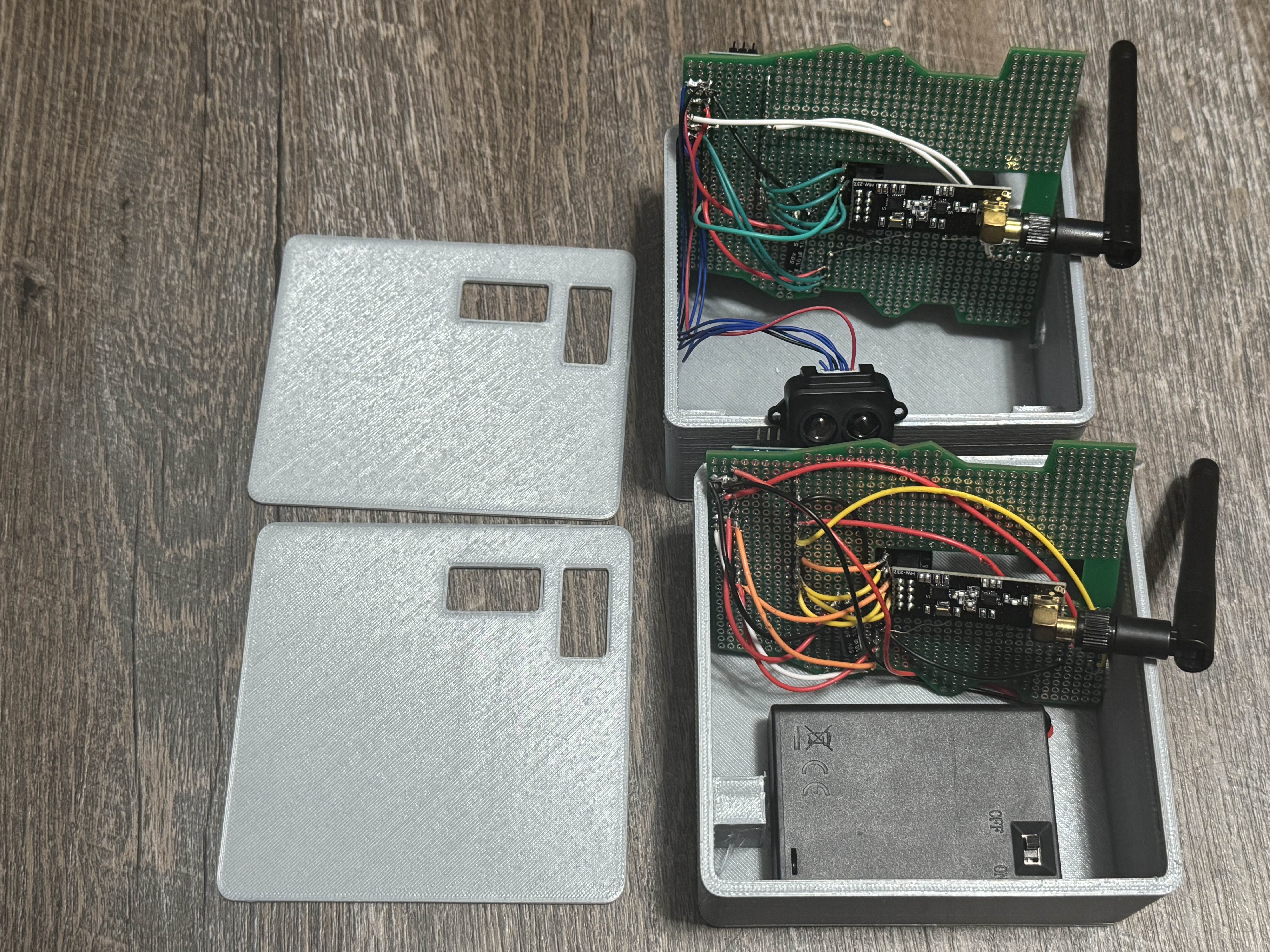
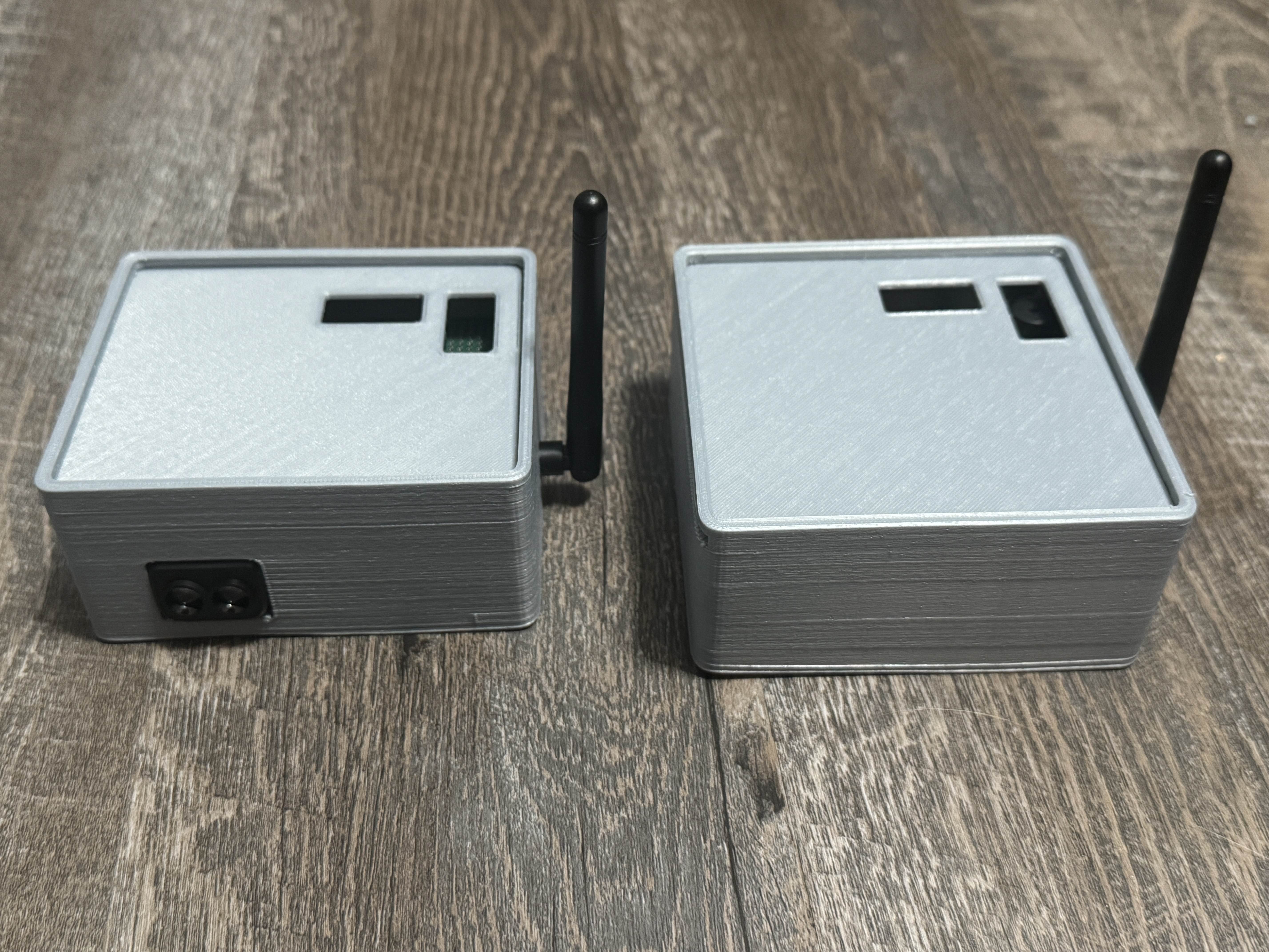
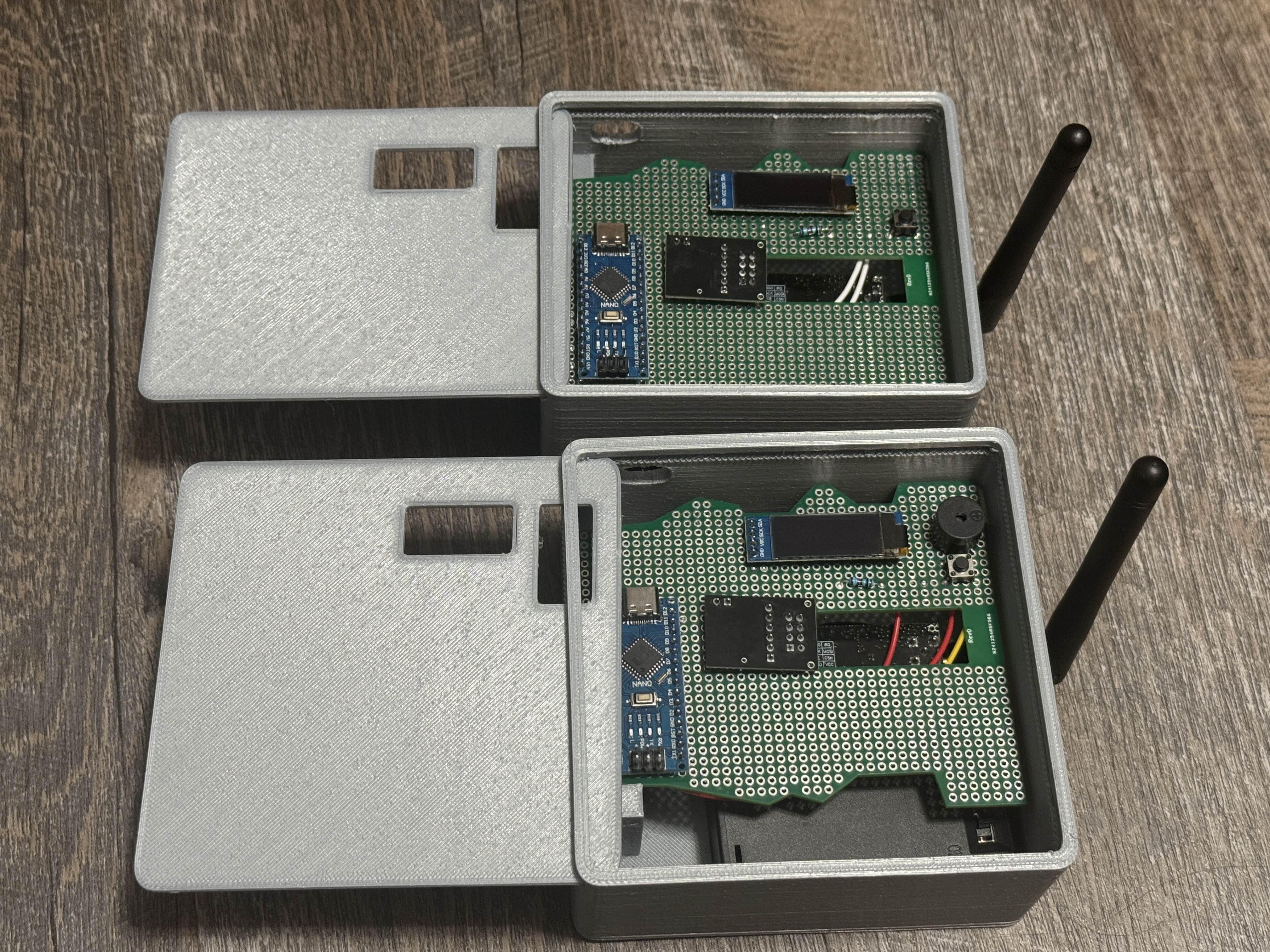
Soldering the components to a board was a bit tedious. My soldering station had a pair of helping hands, I’m not sure if I could have done it without them. I individually cut and stripped each wire, and soldered the components to the board. Below are the finished boards inside of their cases, which I had to design as well.
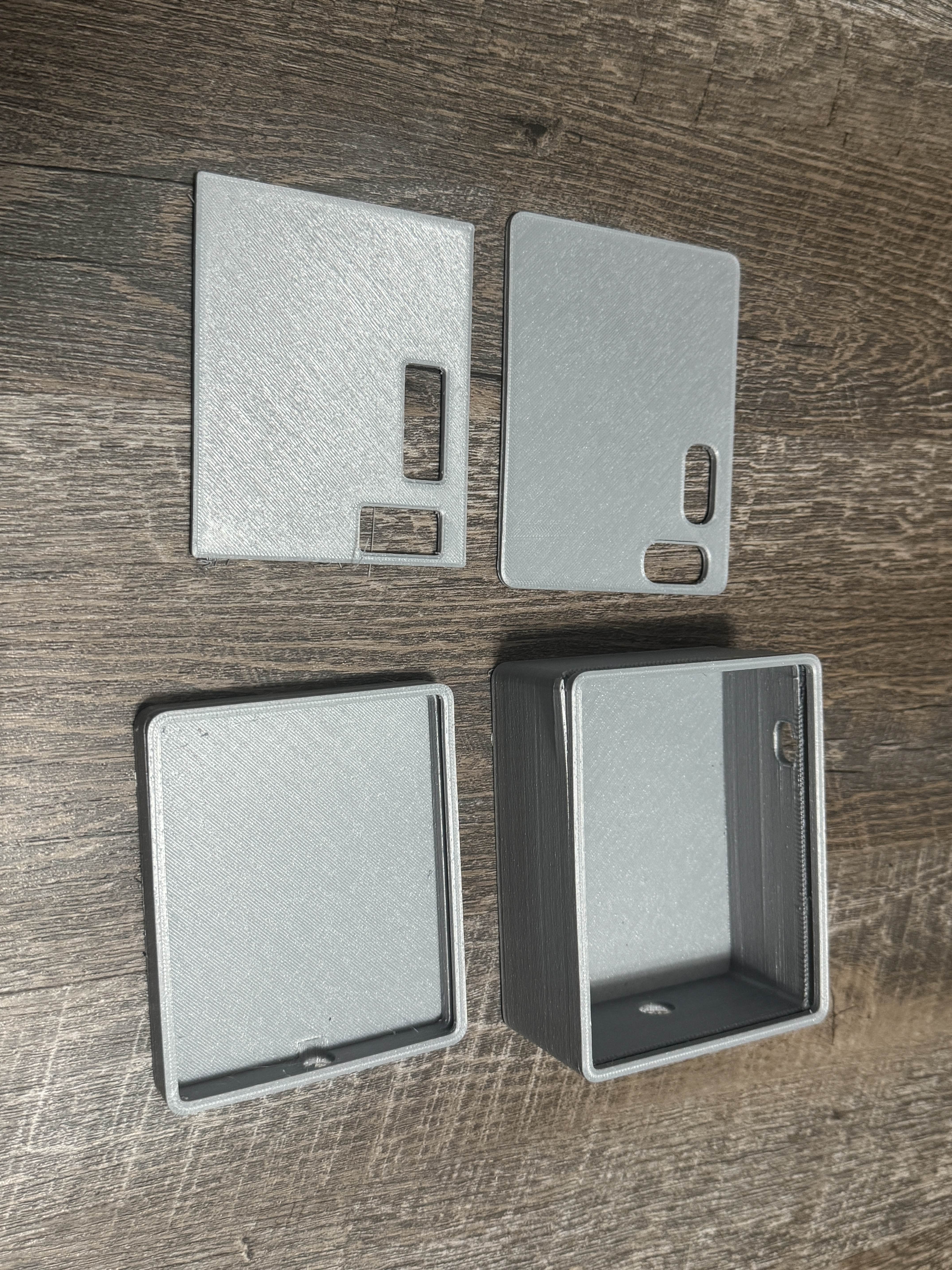
I had experience 3D modeling in Blender, but this wasn’t very similar to what I had modeled before. I was used to modeling and rendering cars and lego sets, not so much in precise CAD work. I started with some videos to get an understanding of what parts I would need to model, most importantly an easy way to access the boards. I decided on a sliding box design, so I created a small box to quickly print and test tolerances. The sliding lid actually worked pretty well on the first attempt, so I decided to print a bigger box to get an idea of how the entire box would work. The second box I printed gave me important information, even though it was a failure almost all around. Even though it should be common sense, it taught me to double check all of my tolerances before printing, because I forgot to make the lid thinner than the opening. The lid printed at the exact same height as the opening, which added stress and cracked the box. These two test boxes are pictured below.
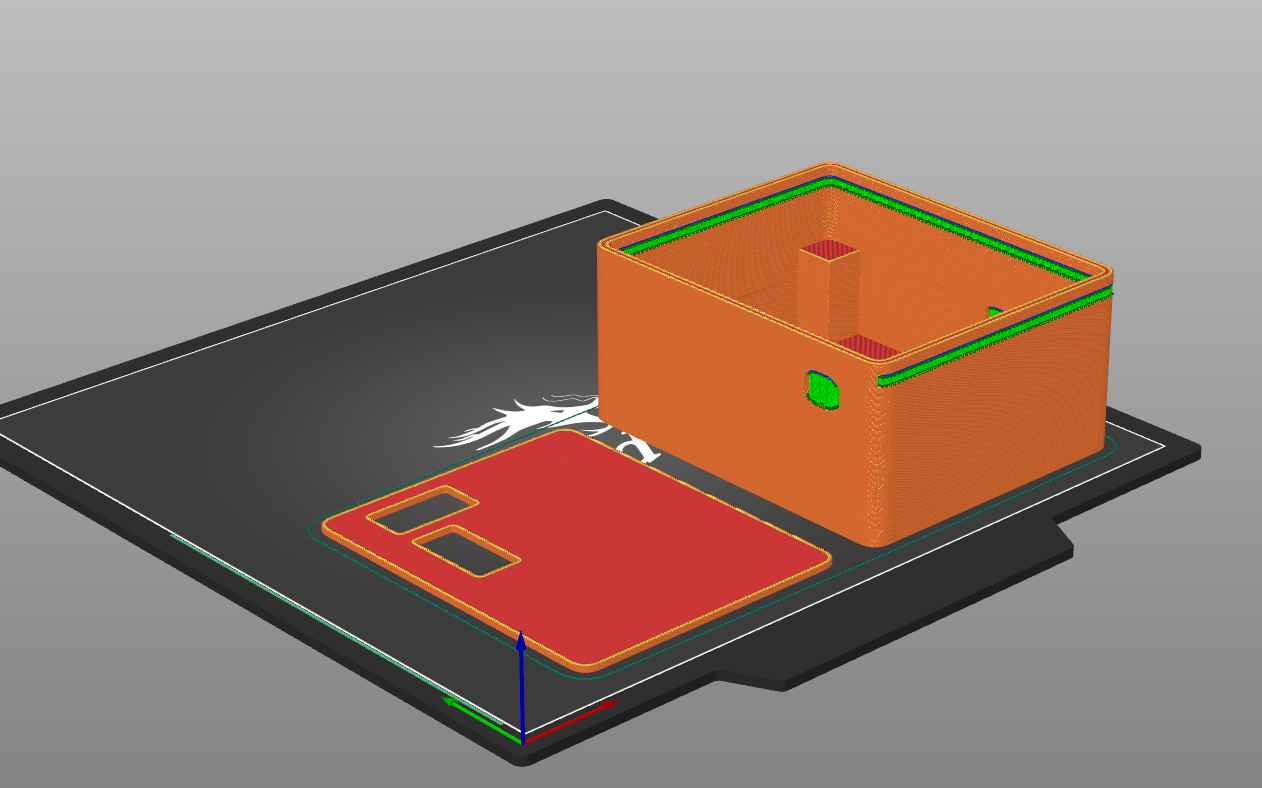
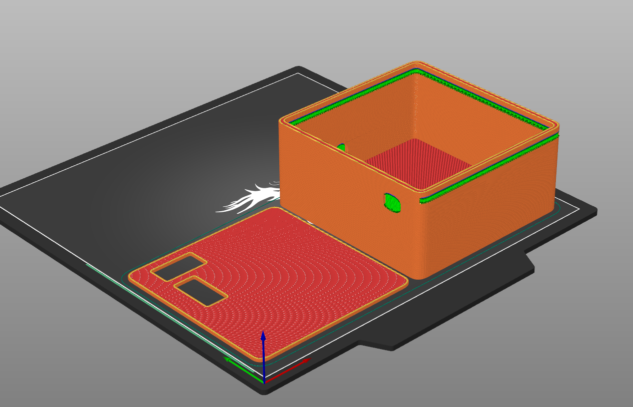
 After some more tweaking, I eventually had a solid design for the boxes, pictured below along with their 3D models in my slicing software.
I am really happy with how this project turned out, and I was able to take it to the track and get some times. The entire design process was super interesting, and it was something new to me. I got significantly better at soldering, learned some more 3D modeling skills, and got to finish the project with a cool physical product. The circuit diagram and code are listed below.
I am mostly focusing on school now, so I haven’t done much work on this project since I finished it, but I plan to refine this project in the future. I have plans to make a time-logging software in python, as well as make some of the code more efficient.
Receiver:
#include <SPI.h>
#include <nRF24L01.h>
#include <RF24.h>
#include <Wire.h>
#include <Adafruit_GFX.h>
#include <Adafruit_SSD1306.h>
#include <TFLI2C.h>

#define SCREEN_WIDTH 128
#define SCREEN_HEIGHT 32
#define OLED_ADDRESS 0x3C

RF24 radio(9, 10);
const byte address[6] = "TIMER";
Adafruit_SSD1306 display(SCREEN_WIDTH, SCREEN_HEIGHT, &Wire, -1);

TFLI2C tflI2C;
int16_t tfDist;
int16_t tfAddr = TFL_DEF_ADR;
const int triggerDistance = 100;

bool raceStarted = false;
bool raceStopped = false;
unsigned long syncedStartTime = 0;
unsigned long localStartTime = 0;

void showMessage(const char* msg, const char* msg2 = nullptr) {
  display.clearDisplay();
  display.setCursor(0, 0);
  display.println(msg);
  if (msg2) display.println(msg2);
  display.display();
}

void setup() {
  Serial.begin(115200);
  Wire.begin();
  display.begin(SSD1306_SWITCHCAPVCC, OLED_ADDRESS);
  display.setTextSize(1);
  display.setTextColor(SSD1306_WHITE);
  showMessage("Waiting for", "race to start");

  radio.begin();
  radio.openReadingPipe(1, address);
  radio.setPALevel(RF24_PA_HIGH);
  radio.setDataRate(RF24_1MBPS);
  radio.startListening();
}

void loop() {
  if (!raceStarted && radio.available()) {
    unsigned long receivedTime = 0;
    radio.read(&receivedTime, sizeof(receivedTime));

    syncedStartTime = receivedTime;
    localStartTime = millis();
    raceStarted = true;
    showMessage("GO!");
    delay(500);
  }

  if (raceStarted && !raceStopped) {
    unsigned long localNow = millis();
    unsigned long elapsed = (localNow - localStartTime) + syncedStartTime;

    int sec = elapsed / 1000;
    int ms = elapsed % 1000;
    char buf[16];
    snprintf(buf, sizeof(buf), "Time: %d.%03d s", sec, ms);
    showMessage("Running...", buf);

    if (tflI2C.getData(tfDist, tfAddr)) {
      if (tfDist > 0 && tfDist < triggerDistance) {
        raceStopped = true;
        showMessage("FINISHED", buf);
      }
    }
  }
}
Sender:
#include <SPI.h>
#include <nRF24L01.h>
#include <RF24.h>
#include <Wire.h>
#include <Adafruit_GFX.h>
#include <Adafruit_SSD1306.h>

#define SCREEN_WIDTH 128
#define SCREEN_HEIGHT 32
#define OLED_ADDRESS 0x3C
#define BUTTON_PIN 3
#define BUZZER_PIN 4

RF24 radio(9, 10);
const byte address[6] = "TIMER";
Adafruit_SSD1306 display(SCREEN_WIDTH, SCREEN_HEIGHT, &Wire, -1);

bool raceStarted = false;
bool raceStopped = false;
unsigned long startTime = 0;

void showMessage(const char* msg, const char* msg2 = nullptr) {
  display.clearDisplay();
  display.setCursor(0, 0);
  display.println(msg);
  if (msg2) display.println(msg2);
  display.display();
}

void setup() {
  pinMode(BUTTON_PIN, INPUT);
  pinMode(BUZZER_PIN, OUTPUT);
  digitalWrite(BUZZER_PIN, LOW);

  Wire.begin();
  display.begin(SSD1306_SWITCHCAPVCC, OLED_ADDRESS);
  display.setTextSize(1);
  display.setTextColor(SSD1306_WHITE);
  showMessage("Waiting to start...");

  radio.begin();
  radio.openWritingPipe(address);
  radio.setPALevel(RF24_PA_HIGH);
  radio.setDataRate(RF24_1MBPS);
  radio.stopListening();
}

void loop() {
  if (!raceStarted && digitalRead(BUTTON_PIN) == HIGH) {

    showMessage("GETTING READY");
    tone(BUZZER_PIN, 100, 200);
    delay(10000);

    showMessage("On your marks...");
    tone(BUZZER_PIN, 100, 200);
    delay(15000);

    showMessage("Set...");
    tone(BUZZER_PIN, 100, 200);
    delay(1500 + random(500, 2000));

    showMessage("GO!");
    tone(BUZZER_PIN, 200, 400);
    startTime = millis();
    raceStarted = true;
  }

  if (raceStarted && !raceStopped) {
    unsigned long raceTime = millis() - startTime;
    radio.write(&raceTime, sizeof(raceTime));

    int sec = raceTime / 1000;
    int ms = raceTime % 1000;
    char buf[16];
    snprintf(buf, sizeof(buf), "Time: %d.%03d s", sec, ms);
    showMessage("Running...", buf);

    delay(1);
  }
}